The power-on test of the PLC control cabinet is an important part to ensure its normal operation and safety. The following is the relevant content of the pre-power-on inspection and post-power-on test:
Pre-power-on inspection
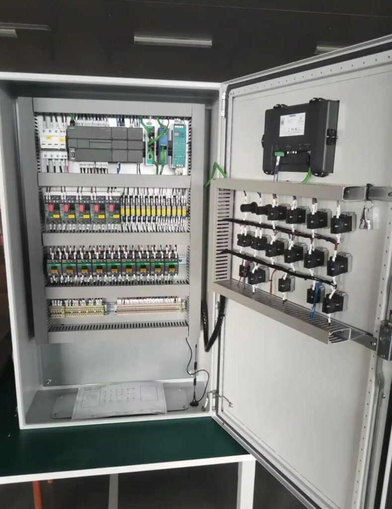
Appearance and installation inspection
Check whether the appearance of the control cabinet is damaged or deformed, whether the cabinet door switch is flexible, and whether the door lock is normal.
Check whether the internal electrical components are installed firmly, whether there is any looseness or displacement, whether the connection lines are neat and beautiful, and whether the markings are clear.
Wiring inspection
Compare the electrical schematic and wiring diagram, check the power lines, signal lines, control lines, etc. in the PLC control cabinet one by one to ensure that the wiring is correct and there is no missing or wrong connection.
Check whether the pressure line of the terminal is firm, whether there is any virtual connection, burrs, etc., to prevent heating or sparking due to poor contact.
Power supply inspection
Confirm whether the voltage level of the input power supply is consistent with the voltage required by the PLC control cabinet. Generally, AC220V or AC380V is common.
Check whether the phase sequence of the power supply is correct, especially for systems that require forward and reverse control such as motors. Wrong phase sequence may cause the motor to reverse or even damage the equipment.
Use a multimeter to measure whether the power supply voltage is within the allowable fluctuation range. Generally, the voltage fluctuation range is required to be within ±10% of the rated voltage.
PLC inspection
Check whether the model and specifications of the PLC are consistent with the design requirements, whether the modules are installed correctly, and whether the connections between the modules are reliable.
Check whether the PLC battery is installed correctly and whether the power is sufficient. For PLC systems that require battery backup data, insufficient battery power may cause data loss.
Check whether the program memory of the PLC has been correctly written into the program. You can check it online or offline through the PLC programming software.
Test after power on
Power supply test
Measure the input power supply voltage to ensure that it is within the working voltage range of the PLC control cabinet. Generally, the allowable fluctuation range of AC220V power supply is ±10%, that is, 198V – 242V; the allowable fluctuation range of AC380V power supply is ±10%, that is, 342V – 418V.
Check whether the output voltage of the power module is normal. The voltage deviation of the common DC24V output power supply should generally be within ±5%, that is, 22.8V – 25.2V.
PLC basic function test
Check the operating status of the PLC through the programming software to ensure that the PLC is in normal operation mode and there is no error alarm information.
Test the input and output points of the PLC. You can force the input signal to observe whether the corresponding output point acts according to the program logic, and vice versa, to check whether the input and output modules are working normally.
Check whether the communication between PLC and host computer or other intelligent devices is normal. You can verify it by sending and receiving data. If you can read and write data normally, it means that the communication function is normal.
Relay and contactor test
Observe whether the pull-in and release actions of relays and contactors are normal after power-on, and whether there are abnormal sounds and vibrations.
Measure the contact voltage and current of relays and contactors to ensure that they are within the normal working range, the contact contact is good, and there is no sparking or arcing.
Protection function test
Simulate overload, short circuit, undervoltage and other fault conditions to check whether the protection circuit of the PLC control cabinet can act in time, cut off the power supply or send out an alarm signal.
Check whether the grounding protection is reliable. You can use a ground resistance tester to measure the grounding resistance. Generally, the grounding resistance is required to be no more than 4Ω.