Definition of frequency conversion control cabinet
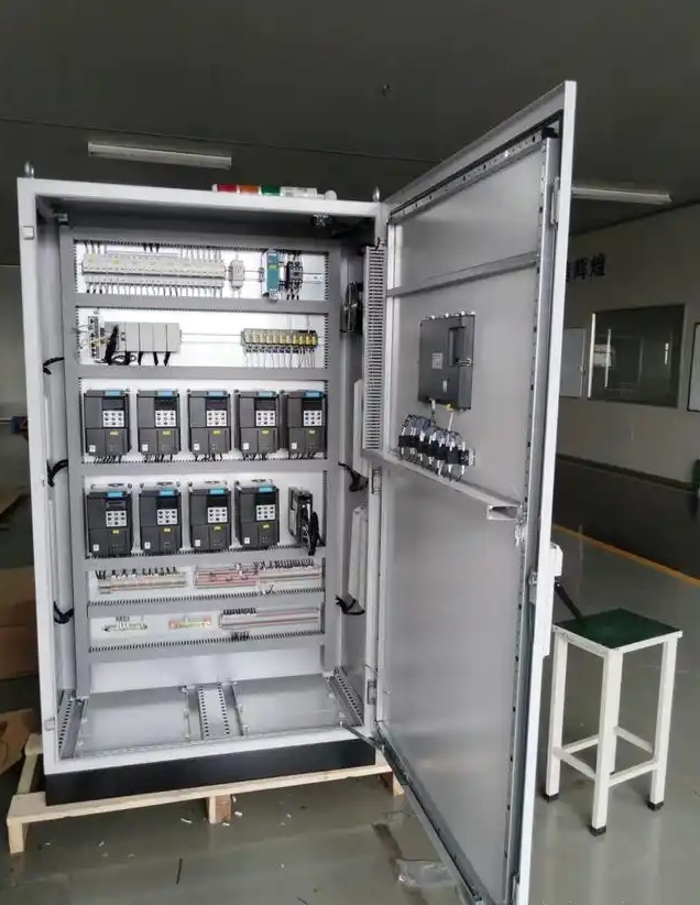
The frequency conversion control cabinet is an electrical control cabinet used to control the running speed of equipment such as motors. It is mainly composed of various electrical components such as frequency converters, circuit breakers, contactors, relays, control buttons, indicator lights, etc. Its core component is the frequency converter, which can realize various functions such as soft start, frequency conversion speed regulation, and energy-saving operation of the motor.
Working principle
Power input and rectification
First, the three-phase AC power supply (usually 380V) is connected to the frequency conversion control cabinet. The rectifier circuit inside the frequency converter converts the input AC power into DC power. This process is mainly completed through the diode rectifier bridge, which converts the three-phase AC voltage into a pulsating DC voltage.
DC filtering
The rectified DC power contains more ripples and needs to be smoothed by filter capacitors to obtain a relatively stable DC voltage. These filter capacitors can store electrical energy, reduce voltage fluctuations, and provide a stable DC power supply for subsequent inverter circuits.
Inversion and frequency conversion output
The filtered DC power enters the inverter circuit. The inverter circuit is composed of power switching devices such as insulated gate bipolar transistors (IGBTs). By controlling the on and off sequence and time of these power switching devices, the DC power is inverted into AC power with adjustable frequency and voltage. The frequency of this AC power can be adjusted according to actual needs, and its output frequency range can generally range from a few Hz to several hundred Hz. For example, when controlling a water pump motor, the motor speed is changed by changing the frequency of the output AC power, thereby adjusting the flow of the water pump.
Control method
The frequency conversion control cabinet uses a built-in controller (which can be a single-chip microcomputer, PLC, etc.) to achieve precise control of the frequency converter. It can receive external signals, such as pressure signals from pressure sensors, speed signals from speed sensors, or manually set operating parameters (such as set speed, frequency, etc.). Based on these signals, the controller calculates the frequency and voltage that the frequency converter should output according to the pre-set control strategy (such as PID control, etc.), and then sends control instructions to the frequency converter to make the motor run at the required speed and torque. For example, in a constant pressure water supply system, when the water pressure drops, the pressure sensor feeds back a signal to the controller, and the controller increases the speed of the motor through the inverter, thereby increasing the water supply pressure of the water pump and restoring it to the set pressure value.