To determine whether the wiring of the PLC control cabinet is correct, you can check from the following aspects:
- Appearance inspection
Check the cable direction:
The cables should be laid neatly and orderly in the control cabinet to avoid crossing and entanglement. A good cable direction is not only convenient for maintenance and management, but also reduces the possibility of electromagnetic interference.
Check whether the cables are properly fixed in the wire trough or cable tie to prevent loosening and falling off.
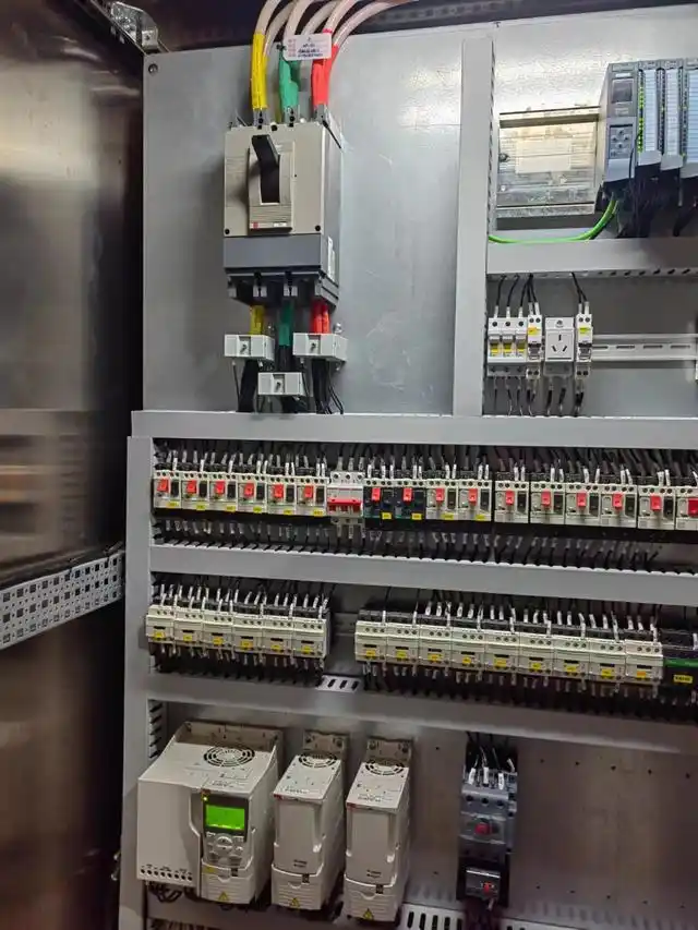
Check the wiring terminals:
The screws on the wiring terminals should be tightened and not loose. Loose screws may cause poor contact, affect signal transmission or cause electrical failures.
Check whether the wires on the wiring terminals are connected correctly and there are no wrong wires. For example, wires of different voltage levels or different signal types should not be connected to the same terminal.
Observe the markings and labels:
The cables and equipment in the control cabinet should have clear markings and labels indicating their names, numbers, uses and other information. This helps to quickly identify and locate problems during inspection and maintenance.
Check whether the markings and labels are consistent with the wiring diagram to ensure the accuracy of the wiring.
- Electrical testing
Measure resistance:
Use tools such as multimeters to measure the resistance between different wires. Under normal circumstances, wires of different voltage levels or different signal types should have a high resistance value, close to infinity. If the measured resistance value is small, there may be a short circuit.
Measure the resistance between adjacent terminals in the same circuit, which should meet the requirements of the circuit design. If the resistance value is abnormal, it may be a wiring error or poor contact.
Check voltage:
Before powering on, use a multimeter to measure the voltage at the input end of the power supply to ensure that the input voltage meets the requirements of the PLC control cabinet. If the input voltage is too high or too low, the equipment may be damaged.
After powering on, measure the output voltage of each output module to check whether it is consistent with the expected output value. If the output voltage is abnormal, it may be a wiring error or module failure.
Test signal:
Use a signal generator or other test equipment to send an analog signal to the PLC input module and observe the response of the PLC control system. If the input signal is normal, but the control system does not act accordingly, it may be a wiring error or a program problem.
For the output module, you can check whether the output signal correctly controls the external device by manual operation or simulating actual working conditions. For example, by pressing a button or switch, observe whether the corresponding relay, contactor, etc. are operating normally.
3. Functional test
Single machine test:
Test each device in the PLC control cabinet, such as PLC modules, relays, contactors, sensors, etc. one by one. Check whether the function of the device is normal and whether it can work as expected.
For some key equipment, a long-term running test can be carried out to observe its stability and reliability.
System joint debugging:
After completing the single-machine test, the system joint debugging is carried out. Connect the PLC control cabinet with external equipment, simulate the actual production process, and check the operation of the entire system.
Observe whether the various indicators of the system meet the design requirements, such as control accuracy, response speed, stability, etc. If problems are found, the causes should be analyzed and adjusted in time.
4. Reference material comparison
Check the wiring diagram:
Compare the actual wiring situation with the designed wiring diagram to check whether the connection of each wire is correct. Pay attention to check whether the symbols, numbers, colors and other information in the wiring diagram are consistent with the actual wiring.
If it is found that the wiring diagram does not match the actual situation, it should be corrected in time, and ensure that the modified wiring diagram is consistent with the actual wiring.
Reference equipment manual:
Check the manuals of PLC modules, sensors, actuators and other equipment to understand the wiring requirements and functional characteristics of the equipment. Check whether the actual wiring is correct by comparing the wiring examples and parameter settings in the manual.
If you encounter problems during the wiring process, you can refer to the troubleshooting section in the equipment manual to find solutions to the problems.
In short, judging whether the wiring of the PLC control cabinet is correct requires comprehensive and detailed inspection and testing. Through methods such as appearance inspection, electrical testing, functional testing, and reference material comparison, problems in the wiring can be effectively discovered and corrected in a timely manner to ensure the normal operation of the PLC control system.

